...
...
...
15.1 Introduction
Ethernet is a computer local area network technology. IEEE's IEEE 802.3 standard sets the technical standard for Ethernet, which specifies the content of the connection, electronic signal and medium access layer agreements including the physical layer. Ethernet is the most popular area network technology currently used, replacing other regional network standards such as Token Ring, FDDI and ARCNET. The standard topology of Ethernet is a bus topology, but the current fast Ethernet (100BASE-T, 1000BASE-T standard) used switch/hub in network connection and organization to increase the network speed, use efficiency and minimize conflicts. As a result, the topology of the Ethernet network becomes a star topology.
Ethernet implements the idea of transmitting information to multiple nodes in the radio system on the network. Each node must obtain cables or channels to transmit information. Each node has a globally unique 48-bit address, which is the MAC address assigned by the manufacturer to the Network Interface Card (NIC). The MAC address is used to ensure that all nodes on the Ethernet can authenticate each other. Because Ethernet is so common, many manufacturers integrate Ethernet cards directly into their motherboards.
This section describes the Ethernet Switch and its associated operational modes. The SP7021 supports a layer 2 (L2) switch (L2SW) with 2 Ethernet ports and 1 SoC port (also called CPU port or NIC port) which acts like a NIC card connected to the 3rd port of switch. The base address for Ethernet Switch Control and Status Registers (CSR) is 0x9C108000 and all registers in the memory map address ranges from 0x9C108000 to 0x9C10827F.
Table 1415-1. shows the key feature of Ethernet hardware (L2SW IP) of SP7021.
switch ports |
|
VLAN |
|
Address table |
|
QoS |
|
LED |
|
Data buffer |
|
System interface |
|
Table 1415-1. Key feature of Ethernet Switch (L2SW IP) of SP7021
...
15.2 Function Diagram
A generalized function diagram of Ethernet L2SW of SP7021 is shown in Figure 1415-1.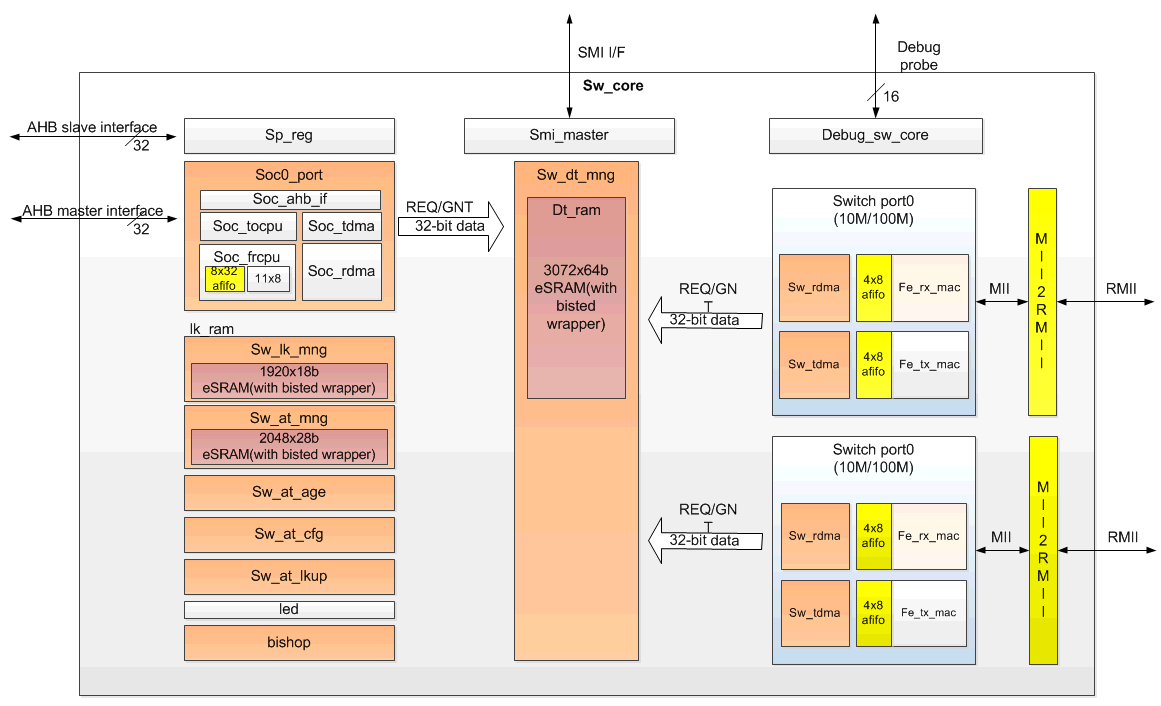
Figure 1415-1 Ethernet Switch (L2SW IP) Block Diagram
Here are descriptions of each block:
...
- sw_port: Switch port0/port1. 10M/100M Ethernet port transceiver.
- sw_dt_mng: Switch data buffer manager.
- soc_port: Soc port, CPU can receive packet from or transmit packet to switch through this port.
- sw_lk_mng: Link manager. It schedules the packet transmit and receive for port0/port1/soc port.
- sw_at_mng: Address table manager. It controls the address table learning and searching.
- sw_at_age: Address table aging control.
- sw_at_cfg: Address table configuration by CPU.
- sw_at_lkup: Address table lookup by CPU.
- Led: LED control. 3 LED for each port.
- bishop: Memory BIST control.
- sp_reg: Switch register file.
- smi_master: Serial management interface master. Switch can polling Ethernet PHY registers through SMI interface.
- Debug_sw_core: Debug control. 16 bits debug probe are provided for debug purpose.
...
15.3 Data Structure
...
15.3.1 Descriptors of Ethernet
The Layer 2 Switch (L2SW) uses descriptors to control transmission and reception of packets between CPU interface and 2 Ethernet ports. Software allocates and initializes memory for descriptors. Descriptors consists of many fields which instructs Ethernet hardware where and how to get or store data for transmission and reception. The Ethernet hardware reads descriptors and uses the allocated memory to access data. Descriptors should be allocated continuously in the memory by software called descriptor queue and the Ethernet hardware uses these descriptors in order. Figure 1415-2 illustrates the relationship between descriptors and data buffers.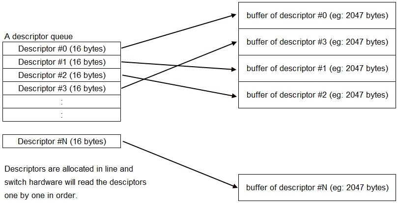
Figure 1415-2 Descriptors of L2SW
...
15.3.2 TX Descriptor
Ethernet hardware supports 2 descriptors queue for transmission and 2 descriptors queue for reception. One descriptor queue is for low-priority packets and the other is for high-priority packets. Packets with high-priority tagged will be received and placed on high-priority queue and other packets will be received and placed on low-priority queue during reception. For transmission, software decides which queue the packets will be placed in. Figure 1415-3 shows the detailed field definition of transmission (TX) descriptor.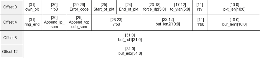
Figure 1415-3 Field definition of TX descriptor
Here are detailed description of each field:
...
- to_vlan: the vlan member set index, the packet forward to the designated VLAN group.
- pkt_length: tx_len_r, the length of the current packet
- ring_end: end of the descriptor ring
- append_ip_sum: append IP checksum
- append_tcpudp_sum: append tcp/udp checksum (not implemented yet)
- buf2_length: buf2 length. Each descriptor can support two buffers, if the tx_length > buf1_length, then get the rest data from buf2.
- buf1_length: buf1 length.
- buf1_addr: buf1 address.
- buf2_addr: buf2 address.
...
15.3.3 RX Descriptor
Figure 1415-4 shows the detailed field definition of reception (RX) descriptor.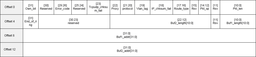
Figure 1415-4 Field definition of RX descriptor
Here are detailed description of each field:
...
- Others: reserved
- pkt_lenth: length of current packet
- ring_end: end of the descriptor ring
- buf2_length: buf2 length. Each descriptor can support two buffers, if the rx_len_r > buf1_length, then put the rest data to buf2.
- buf1_length: buf1 length.
- buf1_addr: buf1 address.
- buf2_addr: buf2 address.
...
15.4 Ethernet Switch Function with Address Table
The switch used in the Ethernet network can increase the available bandwidth of the network, and can also analyze the MAC address of the source end and the destination end according to the sent network packet, and create a MAC address table, and the network packet is correctly forwarded by such a MAC address table.
Although the switch is the second layer operating in the network seven-layer architecture, due to the switch has a higher speed internal structure and a larger number of interfaces, so it can provide more network traffic compared with the traditional gateway.
Regarding the learning of MAC addresses, the switch will listen to the incoming frames from their peers (called the Frame through the network packet of the switch), detect the source MAC address of these data, and recorded the correspondence of the MAC address and port number in the local MAC database. This MAC database is usually called MAC Address Table.
When the switch receives the Frame again, it will first go to the MAC database to see which node to go to the machine specified by the destination MAC address. If the destination MAC address can be found in the MAC database, then This Frame will only be forwarded from the learned port. If such a correspondence is not found in the MAC database, the Frame will be forwarded from all other ports (except sources).
SP7021 can supports up to 1K MAC address table entries. Figure 1415-5 shows the address table format. 
Figure 1415-5 Field definition of address table
Here are detailed description of each field:
- mc_ingr – enable checking the destined port and local port are in the same group for reserved MC.
- Proxy - a packet from CPU port (SoC Port or called Port 3)
- Look up the address table. If the SA is (cpu port=0 or proxy =1)
- Add or update proxy 1 when learning.
- When LAN port receiving a packet.
- Look up the address table.
- If the DA (proxy bit ==1), then add a proxy bit ==1 to link table.
- AHB port transmitting a packet to Port3 will add a proxy bit to descriptor.
- Age – aging bit – The field will be 001 when a valid address is learned. It will increase by one. Once the 60 sec counter pulse is reached. When the field = 110 and the 60 sec counter pulse comes, it will wrap to 000 and the address will be aged out.
- Vid_index – VLAN member set index field.
- soc0_port – the learned port is soc0 port
- soc1_port – the learned port is soc1 port
- Reserved for further usage
- Port map – the learned port bit map.
- MAC [38:0] – the MAC address.
...
15.5 Three Operation Modes
Ethernet driver of SP-7021 supports 3 operation modes:
...
In "An NIC with daisy-chain mode", Ethernet driver creates one net-device interface (ex: eth0). The net-device interface is connected to two LAN ports (two RJ45 sockets) via L2 switch. In this mode, a packet from one LAN port will be either forwarded to net-device interface (eht0) if its destination address matches MAC address of net-device interface (eth0), or forwarded to other LAN port. A packet from net-device interface (eth0) will be forwarded to a LAN port if its destination address is learnt by L2 switch, or forwarded to both LAN ports if its destination has not been learnt yet. Figure 15-6 .14-7 illustrates the packets flow in this mode.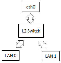
Figure 1415-6 Packets flow in "An NIC with daisy-chain" mode
In "Dual NIC mode", Ethernet driver creates two net-device interfaces (ex: eth0 and eth1). Each has its dedicated LAN port. Packets will not be forwarded between two ports, unless you run some bridge utilities manually. Refer to Figure 1415-7, packets from eth0 will be always forwarded to LAN port 0 and packets from LAN port 0 will be always forwarded to eth0. The same theory is applied for eth1 and LAN port 1.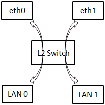
Figure 1415-7 Packets flow in "Dual NIC" mode
"An NIC with daisy-chain mode 2" is similar to "An NIC with daisy-chain mode". The difference is that a packet from net-device interface (eth0) will be always forwarded to both LAN ports. Learning function of L2 switch is turned off in this mode. This means L2 switch will never learn the source address of a packet. So, it always forward packets to both LAN ports. This mode works like you have 2-port Ethernet hub.
...
15.6 L2SW Interrupts
The L2SW interrupt events are connected to the same interrupt vector, please refer to figure 1415-8. These events generate an interrupt if the corresponding "Enable Control Bit" is set. The detail L2SW interrupt information refer to Ethernet Group0.0 sw_int_status_0 register for port0 and Group0.52 sw_int_status_1 register for port1. The enable register is Ethernet Group0.0 sw_int_mask_0 register for port0 and Group0.53 sw_int_mask_1 register for port1.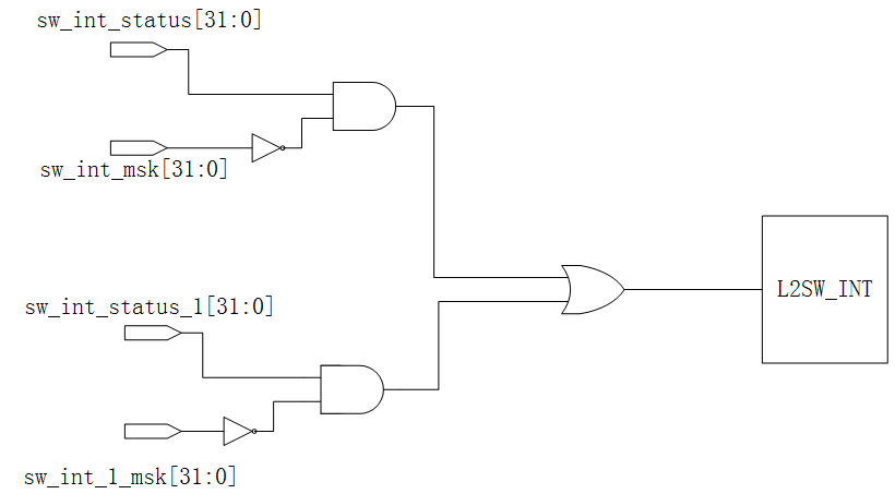
Figure 1415-8 L2SW Interrupt Tree
Table 1415-2/1415-3 shows the Group0.0 sw_int_status_0/Group0.52 sw_int_status_1 registers for each interrupt flag description.
Fields | Fields name | Description |
Bit 31 | daisy_mode_chg | Daisy mode change flag |
Bit 23 | appending_error_0 | IP checksum append error |
Bit 22 | Watchdog1_tmr_expired | Watchdog1_tmr_expired |
Bit 21 | Watchdog0_tmr_expired | Watchdog0_tmr_expired |
Bit 20 | has_intruder | Intruder alert |
Bit 19 | port_st_chg | Port status change |
Bit 18 | bc_storm | BC storm |
Bit 17 | must_drop_lan | Global queue exhausted The must_drop_set_th refer to register Group0.47 flow_ctrl_th3[11:8]. |
Bit 16 | global_que_full | Global queue full (refer to register Group0.2 fl_cntl_th[23:16]). |
Bit 15 | soc_tx_pause_on_0 | Soc port0 transmit pause on |
Bit 14 | soc_qfull_0 | Soc port0 out queue full (Refer to register Group0.3 cpu_fl_cntl_th[15:8]). |
Bit 9 | lan_que_full[1] | port1 out queue full (Refer to register Group0.3 cpu_fl_cntl_th[7:0]). |
Bit 8 | lan_que_full[0] | port0 out queue full (Refer to register Group0.3 cpu_fl_cntl_th[7:0]). |
Bit 7 | L_desc_full_0 | Low priority descriptor full for soc port0 |
Bit 6 | H_desc_full_0 | High priority descriptor full for soc port0 |
Bit 5 | Rx_l_done_0 | Receive low priority descriptor done for soc port0 |
Bit 4 | Rx_h_done_0 | Receive high priority descriptor done for soc port0 |
Bit 3 | Tx_l_done_0 | Transmit low priority descriptor done for soc port0 |
Bit 2 | Tx_h_done_0 | Transmit high priority descriptor done for soc port0 |
Bit 1 | Tx_desc_err_sa_0 | TX descriptor error for soc port0 |
Bit 0 | Rx_desc_err_sa_0 | RX descriptor error for soc port0 |
Table 1415-2 Group0.0 sw_int_status_0 register.
Fields | Fields name | Description |
Bit 23 | appending_error_1 | IP checksum append error |
Bit 15 | soc_tx_pause_on_1 | Soc port1 transmit pause on |
Bit 14 | soc_qfull_1 | Soc port1 out queue full (Refer to register Group0.3 cpu_fl_cntl_th[15:8]). |
Bit 7 | L_desc_full_1 | Low priority descriptor full for soc port1 |
Bit 6 | H_desc_full_1 | High priority descriptor full for soc port1 |
Bit 5 | Rx_l_done_1 | Receive low priority descriptor done for soc port1 |
Bit 4 | Rx_h_done_1 | Receive high priority descriptor done for soc port1 |
Bit 3 | Tx_l_done_1 | Transmit low priority descriptor done for soc port1 |
Bit 2 | Tx_h_done_1 | Transmit high priority descriptor done for soc port1 |
Bit 1 | Tx_desc_err_sa_1 | TX descriptor error for soc port1 |
Bit 0 | Rx_desc_err_sa_1 | RX descriptor error for soc port1 |
Table 1415-3 Group0.52 sw_int_status_1 register.
...
15.7 Registers Map
...
15.7.1 Registers Memory Map
| Address | Group No. | Register Name | Description |
|---|---|---|---|
| 0x9C108000 | G0.0 | sw int status 0 | Interrupt Status 0 |
| 0x9C108004 | G0.1 | sw int mask 0 | Interrupt Mask 0 |
| 0x9C108008 | G0.2 | fl cntl th | Flow Control Threshold |
| 0x9C10800C | G0.3 | cpu fl cntl th | CPU Port Flow Control Threshold |
| 0x9C108010 | G0.4 | pri fl cntl | Priority Flow Control |
| 0x9C108014 | G0.5 | vlan pri th | Vlan Priority Threshold |
| 0x9C108018 | G0.6 | En tos bus | TOS Enable |
| 0x9C10801C | G0.7 | TOS map0 | TOS Map 0 |
| 0x9C108020 | G0.8 | TOS map1 | TOS Map 1 |
| 0x9C108024 | G0.9 | TOS map2 | TOS Map 2 |
| 0x9C108028 | G0.11 | TOS map3 | TOS Map 3 |
| 0x9C10802C | G0.11 | TOS map4 | TOS Map 4 |
| 0x9C108030 | G0.12 | TOS map5 | TOS Map 5 |
| 0x9C108034 | G0.13 | TOS map6 | TOS Map 6 |
| 0x9C108038 | G0.14 | TOS map7 | TOS Map 7 |
| 0x9C10803C | G0.15 | global que status | Global Queue Status |
| 0x9C108040 | G0.16 | addr tbl srch | Address Table Search |
| 0x9C108044 | G0.17 | adr tblst | Address Table Status 0 |
| 0x9C108048 | G0.18 | MAC ad ser0 | Address Table Status 1 |
| 0x9C10804C | G0.19 | MAC ad ser1 | Address Table Status 2 |
| 0x9C108050 | G0.21 | wt mac ad0 | wt mac ad0 |
| 0x9C108054 | G0.21 | w mac 15 0 bus | w mac 15 0 bus |
| 0x9C108058 | G0.22 | w mac 47 16 bus | w mac 47 16 bus |
| 0x9C10805C | G0.23 | PVID config0 | PVID configure 0 |
| 0x9C108060 | G0.24 | Reserved | Reserved |
| 0x9C108064 | G0.25 | VLAN member config0 | VLAN member set config 0 |
| 0x9C108068 | G0.26 | VLAN member config1 | VLAN member set config 1 |
| 0x9C10806C | G0.27 | port ability | port ability |
| 0x9C108070 | G0.28 | port st | port status |
| 0x9C108074 | G0.29 | cpu cntl | CPU port control |
| 0x9C108078 | G0.31 | port cntl0 | port control 0 |
| 0x9C10807C | G0.31 | port cntl1 | port control 1 |
| 0x9C108080 | G0.32 | port cntl2 | port control 2 |
| 0x9C108084 | G0.33 | sw glb cntl | switch global control |
| 0x9C108088 | G0.34 | sw reset | Switch Reset |
| 0x9C10808C | G0.35 | led port0 | LED Port 0 |
| 0x9C108090 | G0.36 | led port1 | LED Port 1 |
| 0x9C108094 | G0.37 | Reserved | Reserved |
| 0x9C108098 | G0.38 | Reserved | Reserved |
| 0x9C10809C | G0.39 | Reserved | Reserved |
| 0x9C1080A0 | G0.41 | watch dog trig rst | Watch dog trigger reset |
| 0x9C1080A4 | G0.41 | watch dog stop cpu | Watch dog stop CPU port receiving |
| 0x9C1080A8 | G0.42 | phy cntl reg0 | PHY control register 0 |
| 0x9C1080AC | G0.43 | phy cntl reg1 | PHY control register 1 |
| 0x9C1080B0 | G0.44 | mac force mode | MAC force mode |
| 0x9C1080B4 | G0.45 | VLAN group config0 | VLAN group port config 0 |
| 0x9C1080B8 | G0.46 | Reserved | Reserved |
| 0x9C1080BC | G0.47 | flow ctrl th3 | Flow control threshold |
| 0x9C1080C0 | G0.48 | queue status 0 | Queue status |
| 0x9C1080C4 | G0.49 | debug cntl | Debug control |
| 0x9C1080C8 | G0.51 | Reserved | Reserved |
| 0x9C1080CC | G0.51 | mem test info | Queue status |
| 0x9C1080D0 | G0.52 | sw int status 1 | Interrupt Status 1 |
| 0x9C1080D4 | G0.53 | sw int mask 1 | sw int mask 1 |
| 0x9C1080D8 | G0.54 | sw global signal | Global Control |
| 0x9C1080DC | G0.55 | Reserved | Reserved |
| 0x9C1080E0 | G0.56 | Reserved | Reserved |
| 0x9C1080E4 | G0.57 | Reserved | Reserved |
| 0x9C1080E8 | G0.58 | Reserved | Reserved |
| 0x9C1080EC | G0.59 | Reserved | Reserved |
| 0x9C1080F0 | G0.60 | Reserved | Reserved |
| 0x9C1080F4 | G0.61 | Reserved | Reserved |
| 0x9C1080F8 | G0.62 | Reserved | Reserved |
| 0x9C1080FC | G0.63 | Reserved | Reserved |
...
| Address | Group No. | Register Name | Description |
|---|---|---|---|
| 0x9C108200 | G0.128 | reserved | Reserved |
| 0x9C108204 | G0.129 | Reserved | Reserved |
| 0x9C108208 | G0.130 | cpu tx trig | CPU transmit trigger demand |
| 0x9C10820C | G0.131 | Tx hbase ad 0 | SoC port0 transmit high level priority descriptor base address |
| 0x9C108210 | G0.132 | Tx lbase ad 0 | SoC port0 transmit low level priority descriptor base address |
| 0x9C108214 | G0.133 | Rx hbase ad 0 | SoC port0 receive high level priority descriptor base address |
| 0x9C108218 | G0.134 | Rx lbase ad 0 | SoC port0 receive low level priority descriptor base address |
| 0x9C10821C | G0.135 | Tx hw ad 0 | SoC port0 transmit high level priority current working descriptor address |
| 0x9C108220 | G0.136 | Tx lw ad 0 | SoC port0 transmit low level priority current working descriptor address |
| 0x9C108224 | G0.137 | Rx hw ad 0 | SoC port0 receive high level priority current working descriptor address |
| 0x9C108228 | G0.138 | Rx lw ad 0 | SoC port0 receive low level priority current working descriptor address |
| 0x9C10822C | G0.139 | cpu port cntl reg 0 | SoC Port0 Control Register |
...
15.7.2 Registers Description
0.0 Interrupt Status Reg 0 (sw int status 0)
Address: 0x9C108000
Reset: 0x0
...